We have been diligently working to improve the build speed of the corridor. There are many processes involved in creating the corridor, and loads of places where we have found opportunities to optimise the code.
We’re happy to report significant speed improvements in Corridor creation from Civil Site Design/Corridor EZ. This is a combination of core software optimisation as well as enabling build options for the user to determine how the corridor is built
Software Optimisation
Firstly, we have optimised the code, full stop.
We went through and trimmed off unnecessary actions we were taking in constructing the corridor, and optimising the creation of assemblies and the process for outputting the corridor.
You will notice we process the corridor twice, a necessary step to accommodate the way programming access functions in Civil 3D. We firstly build the corridor with the assemblies, then we add the target mapping and overrides, then rebuild.
Corridor Build Options to Improve Speed
There are some things we do when we make a corridor to exactly replicate the Civil Site Design model. Some of these things you might not need, or may want to do ‘at the end’ when you are ready to hit the publish button.
Let’s overview them, so you know what you’re able to include or not include in your output. Here are the two key new options in your corridor output:
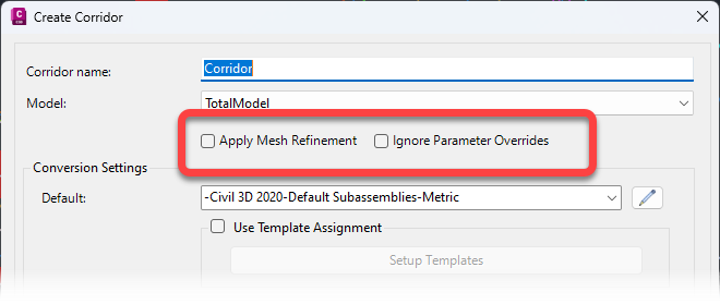
Mesh Refinement
When a Corridor is built from a design model, the software adds extra sampling through the vertical curves to improve accuracy – we call this Mesh Refinement. This process adds time to the corridor build process.
When we add sections, we add them individually because this is how the programming interface is structured. However, as a seasoned corridor user you know you can go in later and increase sampling through vertical curves, so you may want to do this after we have built the corridor for you. Only two words of warning on this: Parameter Overrides. We’ll cover that next.
Adding Mesh Refinement adds more sections to the corridor – if you think you don’t need them, leave this unticked and save time processing sections!
Ignore Parameter Overrides
In the corridor creation process, the software does the following:
- Creates Assemblies at the start of each Road and wherever the cross section Codes change (Codes are added or removed). So, we create a Region at each intersection because we strip away the Codes outside of the edge of the pavement, for the kerb pavement to match in
- Applies Target mapping wherever you’ve requested Code/s on the cross section to adopt the offset of an alignment, the offset and elevation of a String, or the offset of a polyline (we create an alignment over the top of the polyline and target to that)
- Applies Parameter Overrides wherever you’re manually managing the width or slope. Classics for this include the Linearly Vary Width/Slope variation, Match to Surface, Match Slopes and Batter Override. If you are expecting a unique calculation of slopes or widths per section, you’re probably going to see this handled with Parameter Overrides. Outside of alignment/polyline control, any linear editing of widths will trigger parameter overrides.
Parameter Overrides are handled on a section-by-section basis in the corridor. You get to override the inputs of any aspect of the subassemblies applied at the section.
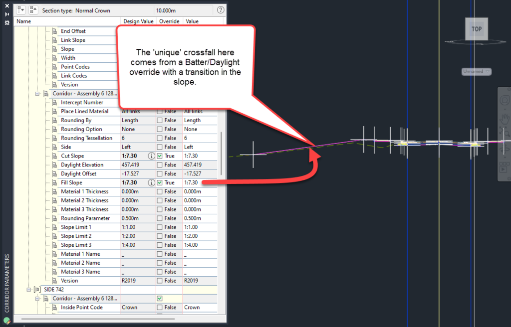
This lets you uniquely control the outputs, section by section. But, it does take time to process.
If you haven’t applied cross section edits warranting Parameter Overrides, tick to Ignore Parameter Overrides in the corridor output. It’ll be much faster skipping this step. Check the corridor – you’ll see pretty quickly if it matches with your original design!
The latest releases of Civil Site Design V26.10 and Stringer Topo V26.10 are here! These updates focus on addressing customer-reported issues, improving pack mode performance, and introducing new features and efficiency enhancements for working with COGO points and Survey Strings. Civil Site Design V26.10 is available on the following platforms: Civil 3D 2021 to Civil […]
Our streamlined design process shaves hours and days off your Civil 3D projects, including the creation of a Civil 3D Corridor complete with multiple regions, target mapping, and assemblies, at the click of a button. We always aimed to make the corridor like you would, reusing and consolidating similar assemblies wherever possible. So, for the […]