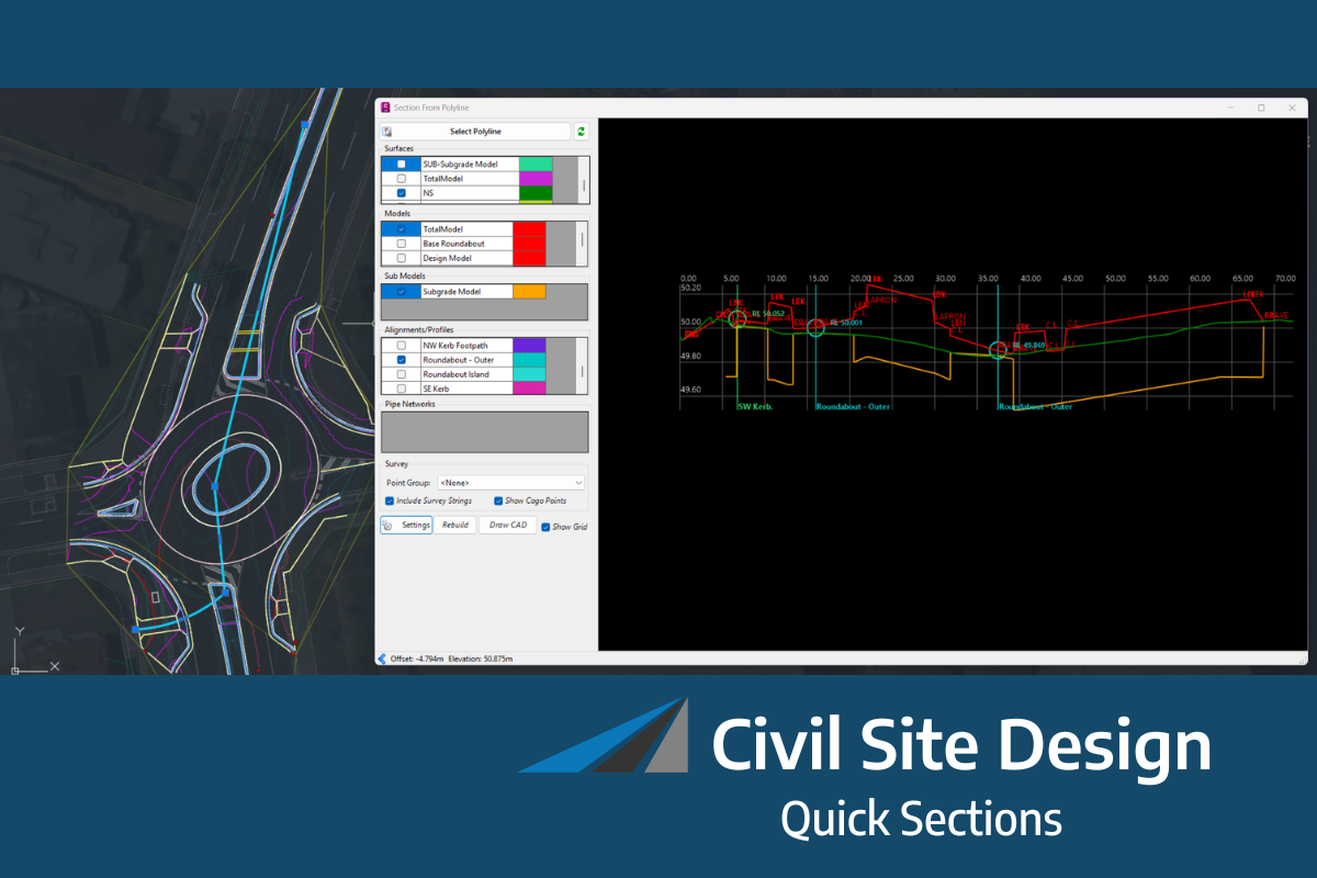
Reference Profiles | Introduction
Reference Profiles are strings that reference the design of a road centreline to vertically represent features of your cross section, such as the left/right kerb lines. You pick the ranges of which to match the road centreline design, and edit the design in between to manage the left/right kerb elevations and road crossfalls through intersections. If you’re in Civil 3D, you can project these directly onto your road alignment as Projected Profiles (complete with IP’s and vertical curves) for plan production.

Reference profiles are a streamlined tool to redesign kerb lines to manage the vertical grading and accommodate for crossfall changes at intersections and anywhere along a road.
Reference Profiles automate multiple tasks in delivering design controls for your roads:
- Creating Strings describing the left/right kerb lines of your road, enabling design control of the kerb lines left/right of your road where you want, and otherwise referencing the Road centreline design
- Automatically applying changes to the road cross sections based on the Reference Profile elevations
- Automating the process of projecting these onto your road alignments as Civil 3D profiles, where it is required to show the kerb profile design/s along with, or instead of, the centreline design
Reference Profiles dynamically reference the road centreline design over chainage ranges you control, allowing for quick creation of road crossfall transitions to meet design requirements where required. For intersection control, you can specify an intersection match code to ensure proper alignment of kerb or edge-of-road profiles with the main road at an intersection.
Reference Profiles can be created individually or all at once using the Auto Create function.
You pick all the roads you need to create profiles for, the codes you are designing from the road, whether you want to immediately create profile views, and whether to create projected profiles.The command will do the rest, setting up the ranges to reference the road centreline, adding the vertical connections through intersections, applying the new kerb controls to the road and optionally producing Civil 3D profiles.
You can edit the Reference Profile Strings using the Vertical Grading Editor to adjust the vertical design where you need.
The latest releases of Civil Site Design V26.10 and Stringer Topo V26.10 are here! These updates focus on addressing customer-reported issues, improving pack mode performance, and introducing new features and efficiency enhancements for working with COGO points and Survey Strings. Civil Site Design V26.10 is available on the following platforms: Civil 3D 2021 to Civil […]
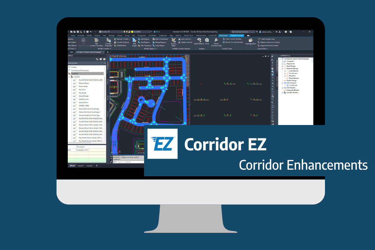
Our streamlined design process shaves hours and days off your Civil 3D projects, including the creation of a Civil 3D Corridor complete with multiple regions, target mapping, and assemblies, at the click of a button. We always aimed to make the corridor like you would, reusing and consolidating similar assemblies wherever possible. So, for the […]