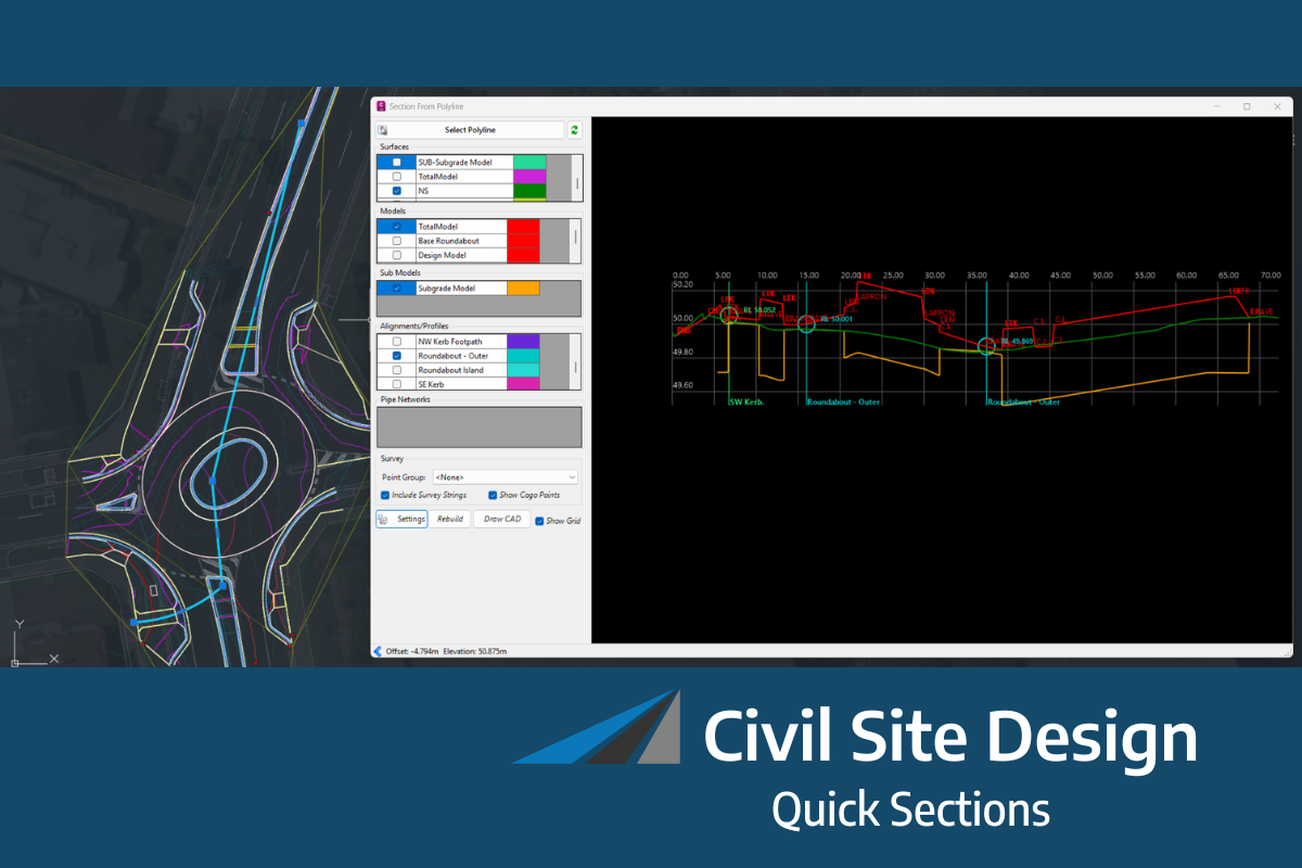
Sectional Volumes | Introduction

- Live Subgrade View: When you select a chainage on a string, the tool presents a live view of the subgrade template applied to that specific string. Additionally, polygons representing the different areas of cut and fill are displayed.
- Visualisation Tools: The settings tab provides options to toggle the display of subgrade polygons and separate polygons, allowing for clearer visualisation of cut and fill areas.
- Automatic Intersection Trimming: The software automatically trims out the intersection on any road string. This means that the volume calculations are not affected by the subgrade for the kerb/curb return replacing the road subgrade in the intersection area.
- Accurate Subgrade Calculation: The tool only calculates the road subgrade where the road actually begins, taking into account the varying positions of kerb/curb tangent points. This ensures accurate volume calculations.
- Stripping Value Application: If a stripping value is applied through the Design Data Form, it is automatically factored into the calculations for all sections.
Sectional Volumes | Multi Section Viewer
A new multisection viewer provides a comprehensive view of all cross-sections for a selected string in a single environment. This viewer offers:
- Easy navigation functionality.
- Export capability as a DWG file.
- Options to customise spacing and visuals for plotting.

Sectional Volumes | Calculation Method
The sectional volumes tool uses the average end area method to determine the volume of cut or fill between two cross-sections.
The method calculates the area of fill or cut at each cross-section. Then, the average area of the two cross-sections is calculated. This average is then multiplied by the distance between the two cross-sections, producing the volume of cut or fill. This process is repeated for each subsequent cross-section along the alignment, with the cumulative volume of cut or fill being tracked throughout.
The latest releases of Civil Site Design V26.10 and Stringer Topo V26.10 are here! These updates focus on addressing customer-reported issues, improving pack mode performance, and introducing new features and efficiency enhancements for working with COGO points and Survey Strings. Civil Site Design V26.10 is available on the following platforms: Civil 3D 2021 to Civil […]
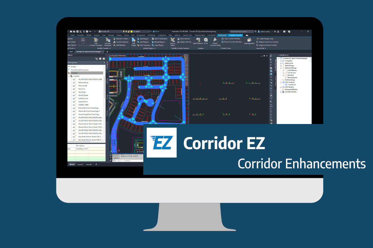
Our streamlined design process shaves hours and days off your Civil 3D projects, including the creation of a Civil 3D Corridor complete with multiple regions, target mapping, and assemblies, at the click of a button. We always aimed to make the corridor like you would, reusing and consolidating similar assemblies wherever possible. So, for the […]