From V26.20 release you now have the ability to quickly extract a dynamic section view along any polyline. This allows designers to quickly visualise and review their designs without the overhead of creating strings.
This command is super simple to use:
– Create a polyline
– Run the Quick Section command and pick the polyline

In the graphics display panel on the right you will see a dynamic cross section displaying multiple data sources: Surfaces, Built Models, Subgrade Models, Alignments, COGO Points and Pipe Networks.
The left side panel allows you to quickly turn the display of objects on/off and set colours for quick identification.
Move your cursor in the section display and track the position in plan with the dynamic chainage (station) tracker
Display Features
Of course, there are settings for you to control how things display, such as text heights and marker sizes.
Surfaces display the section information along the polyline. You can change the colours with the colour swatch next to each surface.
Models display where strings and codes intersect the polyline. You have the added benefit when displaying Models to optionally report the Code and the Slopes for analysis and review.

Pop into the Settings to turn on/off the display of the codes and slopes, as well as set the text sizes.
This applies both to top surface Built Models as well as Subgrade Models.
Alignments are marked with a vertical line and alignment name.
Turning on Pipe Networks will display wherever pipes in the selected network/s cross the section.
COGO points display with a marker and text with number, description and elevation. You see the offset tolerance to display.
Dynamic Updating and Settings Recall
You can move the polyline to update the section information, and there is a refresh button if you change the data while the form is open.
When you select a polyline and set up what information you want displayed, this information is remembered and will be reapplied when you reselect the polyline.
Quick Output
If you want a quick, simple output in your drawing, just click on the CAD Output button and pick a spot in the drawing. This creates a drafting output of the section information directly in the drawing.

The latest releases of Civil Site Design V26.10 and Stringer Topo V26.10 are here! These updates focus on addressing customer-reported issues, improving pack mode performance, and introducing new features and efficiency enhancements for working with COGO points and Survey Strings. Civil Site Design V26.10 is available on the following platforms: Civil 3D 2021 to Civil […]
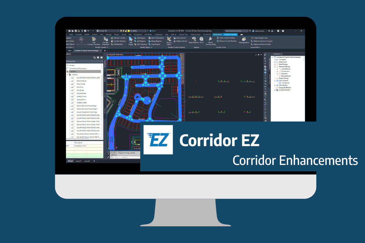
Our streamlined design process shaves hours and days off your Civil 3D projects, including the creation of a Civil 3D Corridor complete with multiple regions, target mapping, and assemblies, at the click of a button. We always aimed to make the corridor like you would, reusing and consolidating similar assemblies wherever possible. So, for the […]
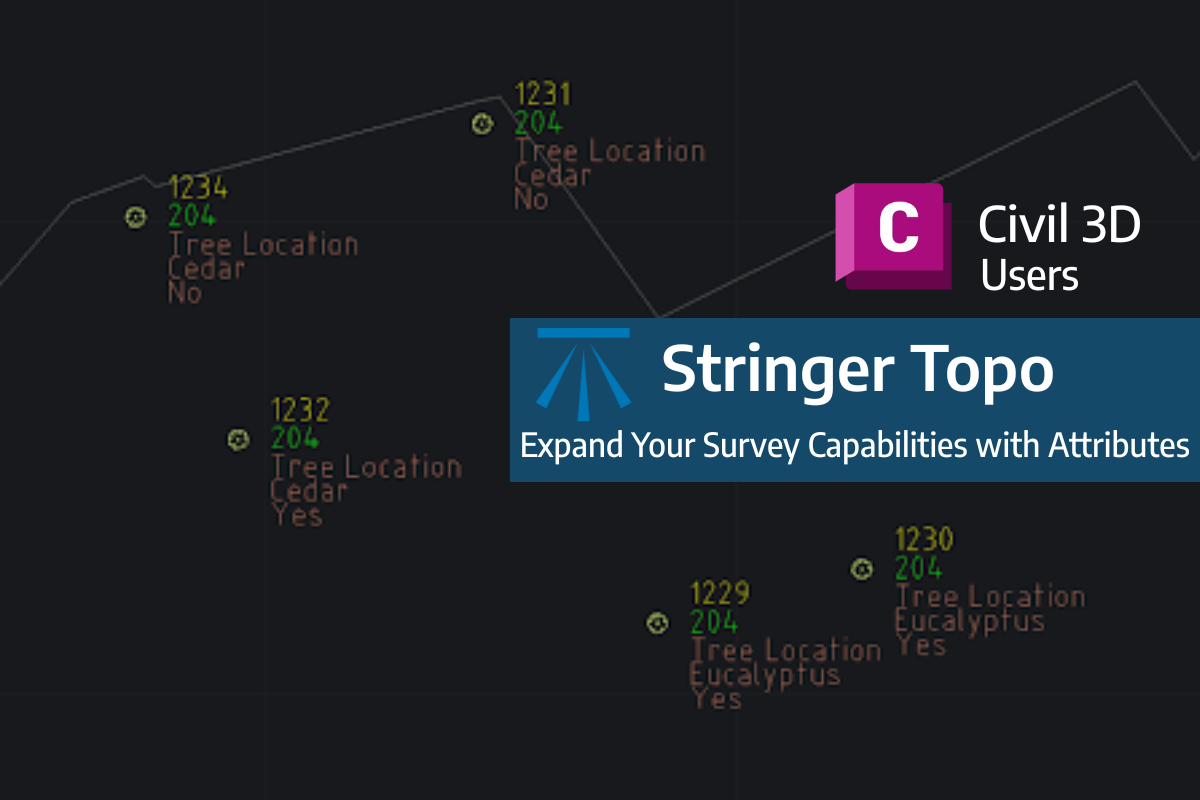
Field attributes provide Surveyors with the ability to include additional data in their Survey pickup of points. With Stringer Topo V26 users can now include additional data (attribute data) with their COGO points and survey strings for review, editing and output from their drawing. There are a number of ways to add attributes to your […]