From V26.20 release you now have the ability to quickly extract a dynamic section view along any polyline. This allows designers to quickly visualise and review their designs without the overhead of creating strings.
This command is super simple to use:
– Create a polyline
– Run the Quick Section command and pick the polyline

In the graphics display panel on the right you will see a dynamic cross section displaying multiple data sources: Surfaces, Built Models, Subgrade Models, Alignments, COGO Points and Pipe Networks.
The left side panel allows you to quickly turn the display of objects on/off and set colours for quick identification.
Move your cursor in the section display and track the position in plan with the dynamic chainage (station) tracker
Display Features
Of course, there are settings for you to control how things display, such as text heights and marker sizes.
Surfaces display the section information along the polyline. You can change the colours with the colour swatch next to each surface.
Models display where strings and codes intersect the polyline. You have the added benefit when displaying Models to optionally report the Code and the Slopes for analysis and review.

Pop into the Settings to turn on/off the display of the codes and slopes, as well as set the text sizes.
This applies both to top surface Built Models as well as Subgrade Models.
Alignments are marked with a vertical line and alignment name.
Turning on Pipe Networks will display wherever pipes in the selected network/s cross the section.
COGO points display with a marker and text with number, description and elevation. You see the offset tolerance to display.
Dynamic Updating and Settings Recall
You can move the polyline to update the section information, and there is a refresh button if you change the data while the form is open.
When you select a polyline and set up what information you want displayed, this information is remembered and will be reapplied when you reselect the polyline.
Quick Output
If you want a quick, simple output in your drawing, just click on the CAD Output button and pick a spot in the drawing. This creates a drafting output of the section information directly in the drawing.

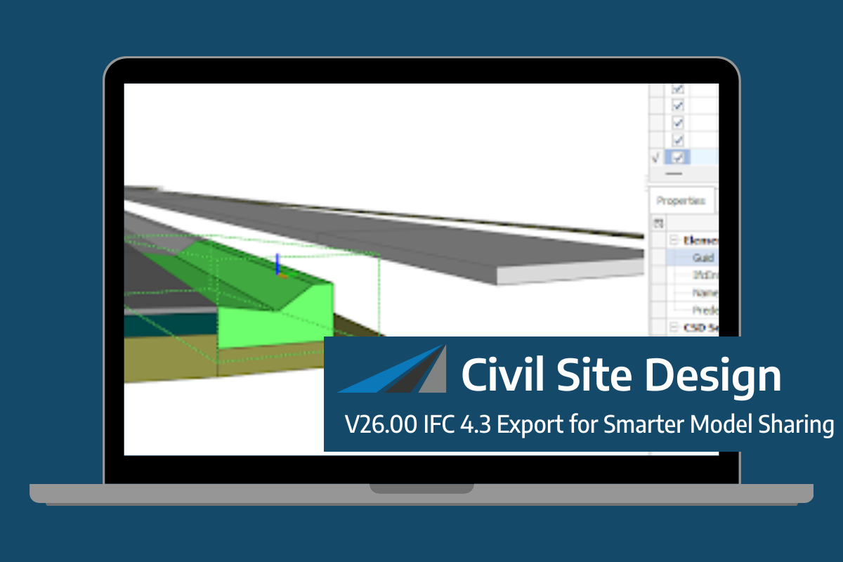
Civil Site Design/Corridor EZ V26 introduces support for IFC 4.3 export, giving users a powerful new way to share detailed 3D models with full classification and geometry data. This enhancement allows designers to export corridor models, road elements, and subgrade components as fully structured, BIM-ready files compatible with a wide range of IFC viewers […]
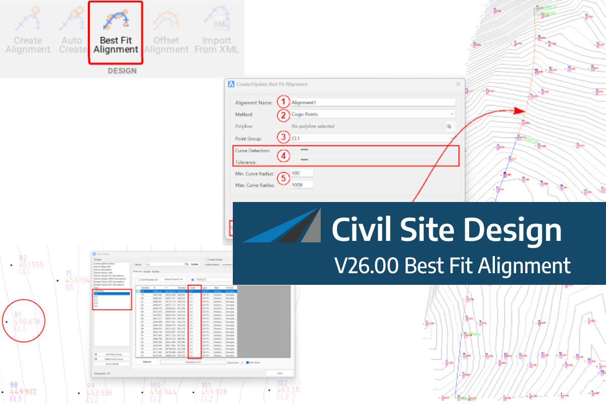
A new feature of Civil Site Design V26 is the Best Fit Alignment command. This command is available to AutoCAD and BricsCAD users and allows you to create an alignment based on Cogo Point or polyline data. When the command is run, the Best Fit algorithm analyses the Cogo Points in the specified Point […]

One of the exciting new features in the Civil Site Design V26 and Stringer Topo V26 release is the Surface from LAS command. Often LiDAR and point cloud data is saved as a LAS file, which previously required interpreting in another software prior to being imported to create a surface. This new command allows you […]
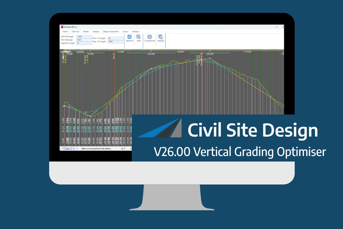
An exciting new tool in Civil Site Design/Corridor EZ v26 is the Vertical Grading Optimizer which can create vertical design profiles based on the parameters you set. Previously, the vertical best fit design profile was based on matching closely to the terrain (within preset cut/fill depths) and adding vertical curves. Mostly, you would remove these […]