The 2027 releases from Autodesk support NET 10, and in this environment serialised files are no longer supported. We use serialised files for different data file storage and settings purposes.
Below is a list of existing files that are converted to comply with .NET10:
CSA Settings folder
These changes apply to new projects (files copied from this Settings folder into new projects) and any project where these settings files are directly accessed
-
PointParameters.dat
-
Manages linework parameters that apply to COGO points
-
Located in the CSA Settings folder
-
-
SurveyStringsSets.dat
-
Manages the automatic creation of survey strings (2D, 3D polylines and breaklines)between COGO Points
-
Located in the CSA Settings folder
-
Also locally stored per project
-
-
Pipe Network Conversion Files
-
These files control the exchange of pipes and structures from Civil Site Design to Civil 3D
-
Located in the CSA Settings folder
-
Original file extension .ncf
-
-
Settings.dat and SettingsUS.dat
-
Manages the FastTrack Settings
-
-
Learning.dat
-
Part of the FastTrack learning system. This file trains FastTrack based on your alignment naming conventions
-
-
subStyles.dat
-
Sets display styles to apply in Subgrade Model Manager
-
-
subgradeSectionStyles.dat
-
Manages the subgrade section styles (determining which codes and layers to include in a subgrade model
-
-
subViewerManager.dat
-
Viewer (Display) settings for Subgrade Model Manager
-
-
gripSettings.dat
-
Manages the grip controls for display of objects in the drawing
-
Local Data files
These changes apply to the current project and changes are made when the project is first opened in V27.00
-
ProjectAssistSettings.dat
-
Local version of settings.dat, managing FastTrack settings in the current project
-
-
subModels.dat
-
Contains the created subgrade models
-
-
subStyles.dat
-
Sets display styles to apply in Subgrade Model Manager
-
-
subgradeSectionStyles.dat
-
Manages the subgrade section styles (determining which codes and layers to include in a subgrade model
-
-
subViewerManager.dat
-
Viewer (Display) settings for Subgrade Model Manager
-
-
bricsCADSurfaceManager.dat
-
Manages the exchange connections between BricsCAD and CSD/Stringer
-
-
mvProfileSectionAnalsysis.dat
-
Manages the Model Viewer surface analysis controls
-
-
pipesVGESettings.dat
-
Display settings in the Pipes VGE window
-
-
Settings.dat
-
Manages the FastTrack Settings
-
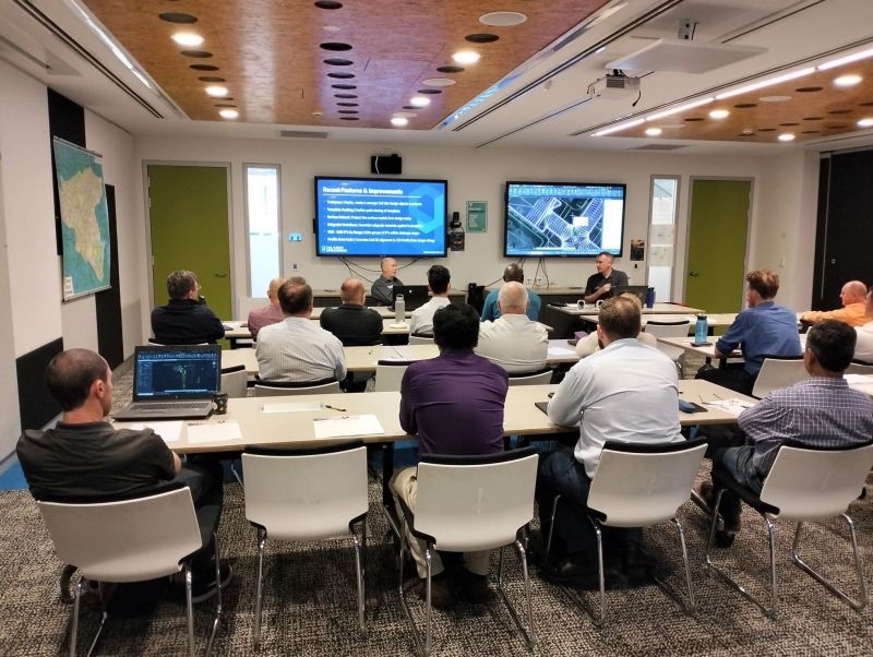
Civil Survey Applications recently hosted the ‘Civil Site Design: Council User Training Day’ in Parramatta, NSW. This complimentary technical training workshop was centred on civil engineering and design for local government users, with a focus on practical application of Civil Site Design features. The agenda was designed to deliver direct value to the attendees through […]

Since releasing Civil Site Design in the USA in 2007, we have experienced constant growth. A technical distributor, Logis LLC, was appointed in 2015, followed by the establishment of Civil Survey Applications LLC in 2019. Located in Florida, the team of 5 including three civil engineers, is committed to customising the software for the US […]
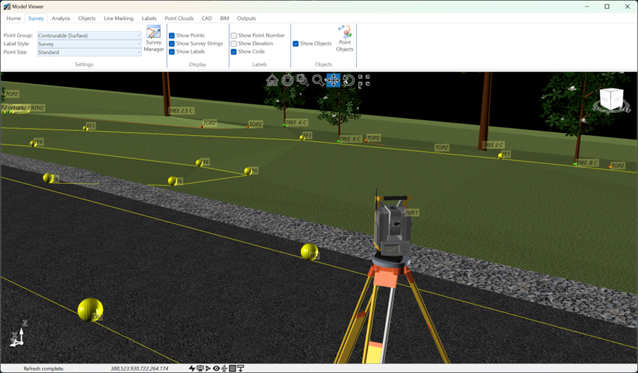
See how Civil Site Design efficiently incorporates and displays survey data, specifically cogo points and survey strings, within your design framework. This article explores this through the lens of a rural road project, demonstrating how cogo points and survey strings from the topographical survey are seamlessly integrated and visualised in Civil Site Design's Cross Section Viewer, VGE (Vertical Grading Editor), and 3D viewer (Model Viewer).
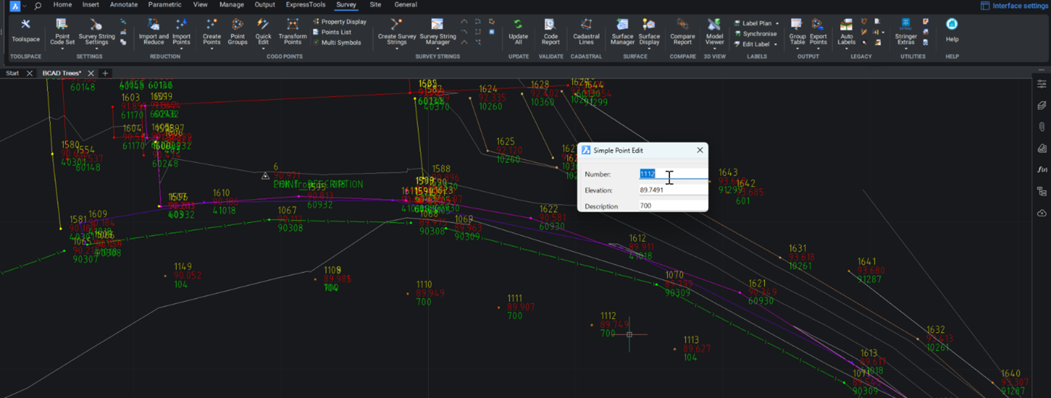
Stringer Topo provides multiple ways for customers to interact with and edit the points and survey strings that define your feature surveys. Using the Survey String Manager, you can select any point or survey string to view properties, and edit the selected object by right click or from the contextual ribbon. The Stringer Toolspace operates as a standard CAD palette, for you to create and edit points, point groups, survey strings and surfaces.