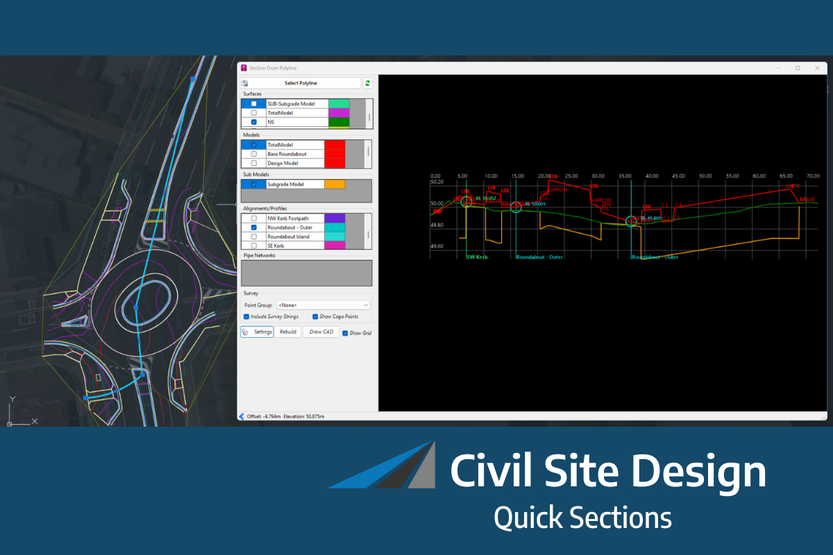
The screen shots and videos below show the functionality operating on Civil Site Design. The same functionality is accessible in Corridor EZ.
Modern civil engineering projects often involve far more than just terrain and corridor models. Designers regularly work with a wide range of 3D CAD geometry, including utility models, structures, architectural elements, bridges, retaining walls, and other project assets.
With Civil Site Design v27, visualisation and sectioning capabilities have been significantly expanded, allowing users to seamlessly integrate native CAD 3D geometry directly into their design workflows.
The result is greater project context, improved design validation, and more comprehensive project reviews.
Expanded Support for Native CAD 3D Geometry
Civil Site Design v27 now supports the visualisation and sectioning of a broad range of native CAD 3D entities alongside Civil Site Design models.
Supported geometry includes:
-
3D Polylines
-
3D Solids
-
Polygon Meshes
-
3DFaces
This expanded compatibility enables designers to work with a much richer representation of the project environment without needing to convert geometry or rely on external workflows.
See Your Entire Project in Context
One of the biggest challenges in design review is understanding how multiple project elements interact within the same space.
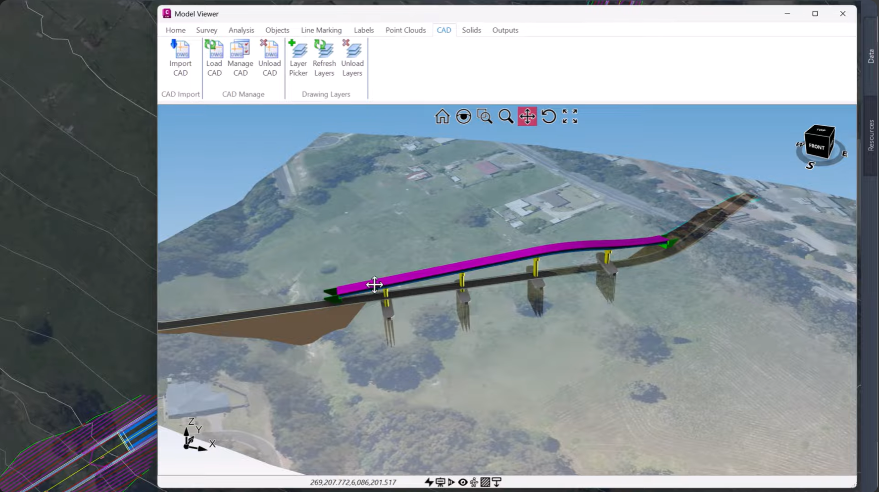
By bringing native CAD geometry into Civil Site Design’s visualisation tools, designers can now view roads, surfaces, drainage infrastructure, structures, and other project assets together in a single environment.
This creates a more complete picture of the design and helps identify potential issues earlier in the project lifecycle.
Whether reviewing site constraints, coordinating infrastructure, or validating design outcomes, having all relevant geometry visible in one place improves decision-making and reduces uncertainty.
Enhanced Model Viewer Integration
The expanded geometry support is fully integrated into the Model Viewer, allowing users to visualise native CAD objects alongside Civil Site Design models in a rich 3D environment.
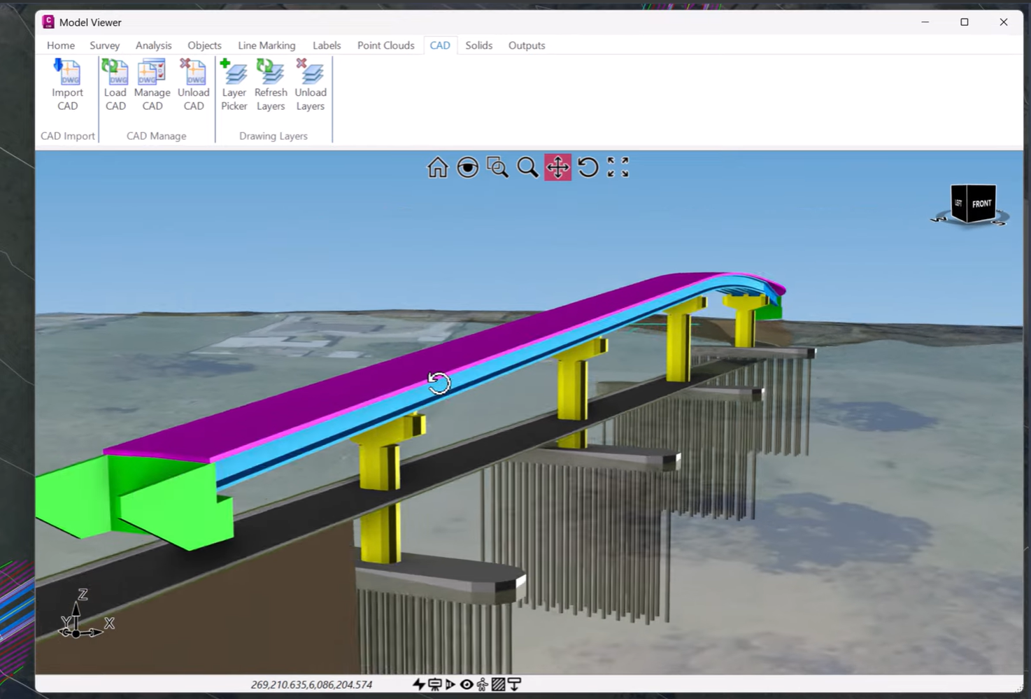
This provides a more realistic representation of the overall project and helps teams better understand how design elements interact within the broader site context.
The ability to combine engineering models with CAD geometry makes the Model Viewer a more powerful design review and presentation tool.
Improved Vertical Grading Workflows
Native CAD geometry can also be visualised directly within the Vertical Grading Editor (VGE).
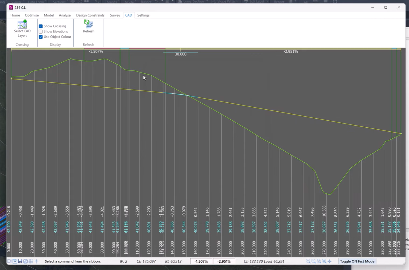
This enhanced visibility provides additional context when developing grading solutions and reviewing vertical design relationships.
Designers can assess grading outcomes against surrounding infrastructure and project elements, helping to improve coordination and reduce design conflicts.
More Powerful Quick Sections
Quick Sections have also been enhanced through support for native CAD geometry.
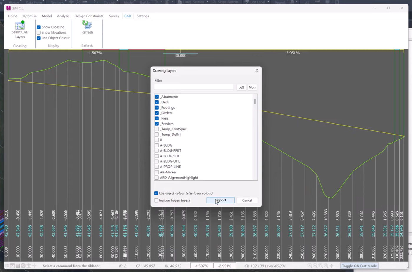
Users can now section through both Civil Site Design models and supported CAD entities within the same workflow, creating a more complete understanding of how various project components interact.
This is particularly valuable when reviewing:
-
Utility corridors
-
Structural interfaces
-
Drainage infrastructure
-
Complex urban environments
-
Multi-disciplinary project models
By incorporating additional project geometry into section views, designers gain deeper insight into the overall design.
Better Coordination Across Disciplines
Civil projects increasingly rely on collaboration between multiple disciplines, each contributing different model types and geometry.
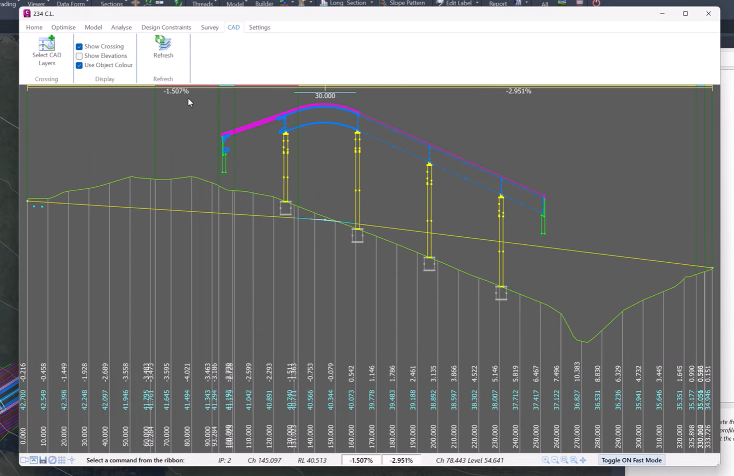
The ability to visualise and section native CAD objects alongside Civil Site Design models helps bridge these workflows by providing a shared environment for design review and coordination.
This reduces the need to switch between platforms and improves communication across project teams.
Key Benefits
-
Visualise native CAD geometry alongside Civil Site Design/ Corridor EZ models
-
Support for 3D solids, polygon meshes, 3DFaces, and 3D polylines
-
Enhanced project context during design reviews
-
Improved coordination between project disciplines
-
Integrated support within Model Viewer
-
Expanded capabilities in the Vertical Grading Editor
-
More comprehensive Quick Section workflows
-
Better validation of design outcomes
A More Connected 3D Design Environment
The expanded 3D capabilities in Civil Site Design v27 provide designers with a more complete view of their projects than ever before.
By bringing native CAD geometry directly into visualisation and sectioning workflows, engineers can better understand project relationships, improve coordination, and make more informed design decisions.
Whether you’re reviewing grading designs, analysing infrastructure interfaces, or presenting project outcomes, Civil Site Design V.27 delivers a more connected and comprehensive 3D design experience.
Available Now in Civil Site Design and Corridor EZ v27
The ability to visualise and section native CAD 3D geometry is available now in Civil Site Design v27 and Corridor EZ.
Explore your projects with greater context, improved visibility, and enhanced coordination by bringing all your key design elements together in a single environment.
The latest releases of Civil Site Design V26.10 and Stringer Topo V26.10 are here! These updates focus on addressing customer-reported issues, improving pack mode performance, and introducing new features and efficiency enhancements for working with COGO points and Survey Strings. Civil Site Design V26.10 is available on the following platforms: Civil 3D 2021 to Civil […]
Our streamlined design process shaves hours and days off your Civil 3D projects, including the creation of a Civil 3D Corridor complete with multiple regions, target mapping, and assemblies, at the click of a button. We always aimed to make the corridor like you would, reusing and consolidating similar assemblies wherever possible. So, for the […]
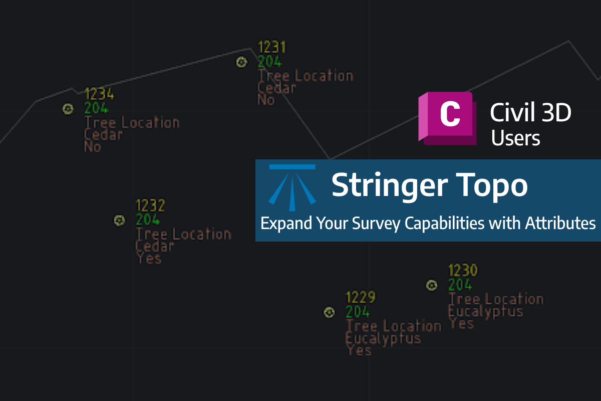
Field attributes provide Surveyors with the ability to include additional data in their Survey pickup of points. With Stringer Topo V26 users can now include additional data (attribute data) with their COGO points and survey strings for review, editing and output from their drawing. There are a number of ways to add attributes to your […]