From V26.20 release you now have the ability to quickly extract a dynamic section view along any polyline. This allows designers to quickly visualise and review their designs without the overhead of creating strings.
This command is super simple to use:
– Create a polyline
– Run the Quick Section command and pick the polyline

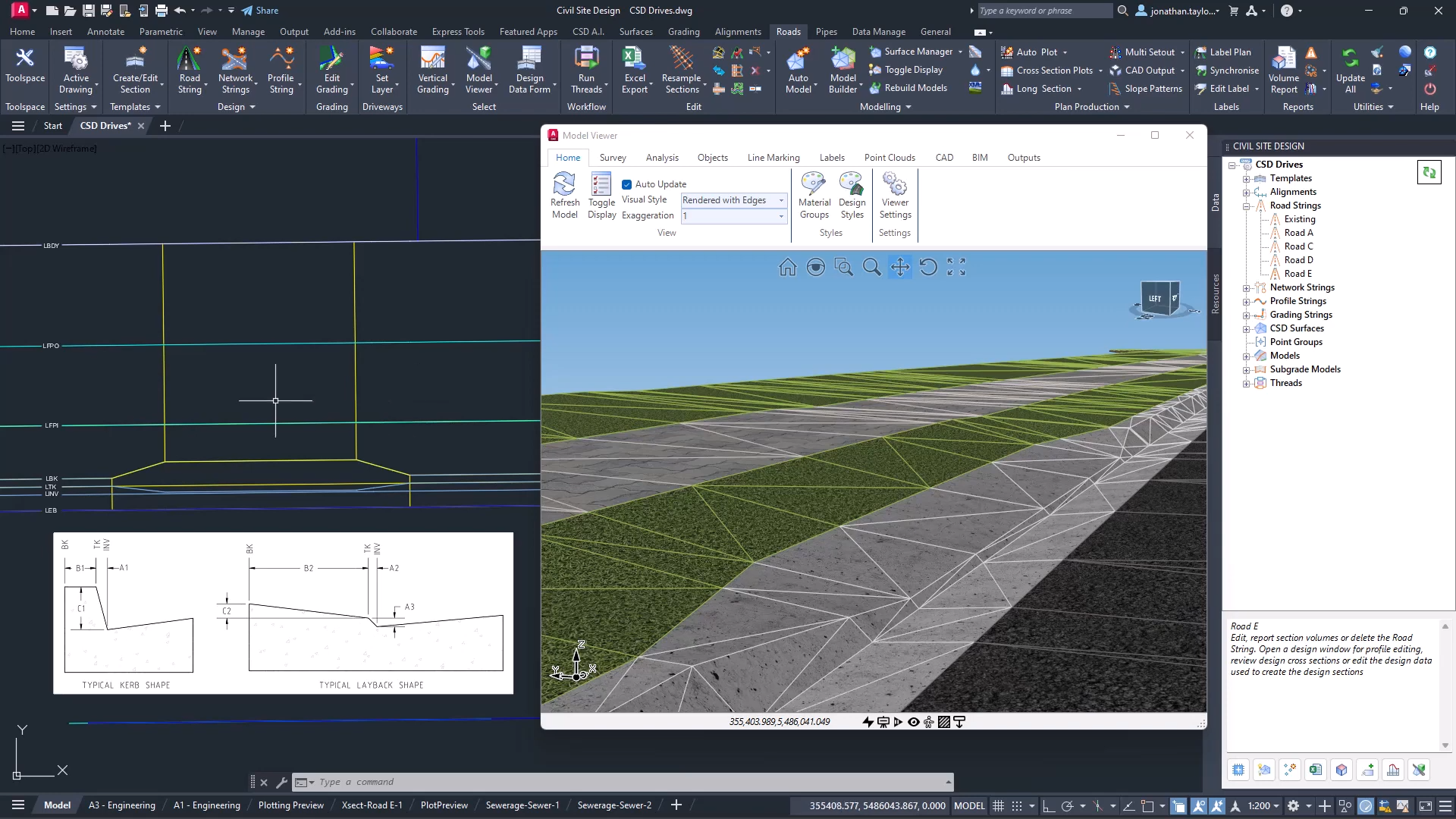
In the graphics display panel on the right you will see a dynamic cross section displaying multiple data sources: Surfaces, Built Models, Subgrade Models, Alignments, COGO Points and Pipe Networks.
The left side panel allows you to quickly turn the display of objects on/off and set colours for quick identification.
Move your cursor in the section display and track the position in plan with the dynamic chainage (station) tracker
Display Features
Of course, there are settings for you to control how things display, such as text heights and marker sizes.
Surfaces display the section information along the polyline. You can change the colours with the colour swatch next to each surface.
Models display where strings and codes intersect the polyline. You have the added benefit when displaying Models to optionally report the Code and the Slopes for analysis and review.

Pop into the Settings to turn on/off the display of the codes and slopes, as well as set the text sizes.
This applies both to top surface Built Models as well as Subgrade Models.
Alignments are marked with a vertical line and alignment name.
Turning on Pipe Networks will display wherever pipes in the selected network/s cross the section.
COGO points display with a marker and text with number, description and elevation. You see the offset tolerance to display.
Dynamic Updating and Settings Recall
You can move the polyline to update the section information, and there is a refresh button if you change the data while the form is open.
When you select a polyline and set up what information you want displayed, this information is remembered and will be reapplied when you reselect the polyline.
Quick Output
If you want a quick, simple output in your drawing, just click on the CAD Output button and pick a spot in the drawing. This creates a drafting output of the section information directly in the drawing.

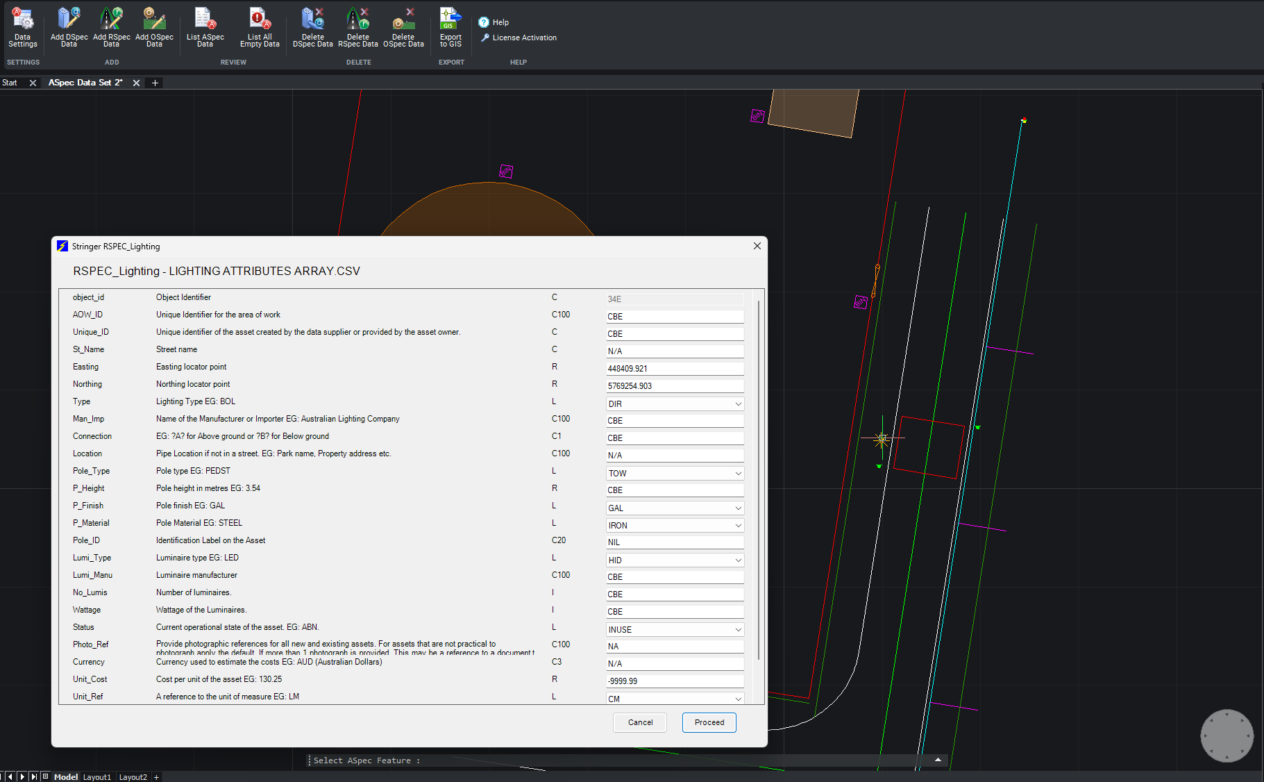
We are pleased to announce the release of Stringer ASpec V24.00. This version includes new features and improvements that aim to streamline ASpec data creation within the CAD environment. Stringer ASpec V24.00 is available on the following platforms: AutoCAD 2018 to AutoCAD 2024 BricsCAD V21 to BricsCAD V24 Civil 3D 2018 to Civil 3D 2024 […]
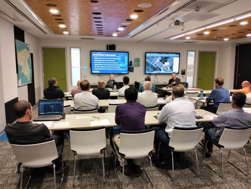
Civil Survey Applications recently hosted the ‘Civil Site Design: Council User Training Day’ in Parramatta, NSW. This complimentary technical training workshop was centred on civil engineering and design for local government users, with a focus on practical application of Civil Site Design features. The agenda was designed to deliver direct value to the attendees through […]

Since releasing Civil Site Design in the USA in 2007, we have experienced constant growth. A technical distributor, Logis LLC, was appointed in 2015, followed by the establishment of Civil Survey Applications LLC in 2019. Located in Florida, the team of 5 including three civil engineers, is committed to customising the software for the US […]