From V26.20 release you now have the ability to quickly extract a dynamic section view along any polyline. This allows designers to quickly visualise and review their designs without the overhead of creating strings.
This command is super simple to use:
– Create a polyline
– Run the Quick Section command and pick the polyline

In the graphics display panel on the right you will see a dynamic cross section displaying multiple data sources: Surfaces, Built Models, Subgrade Models, Alignments, COGO Points and Pipe Networks.
The left side panel allows you to quickly turn the display of objects on/off and set colours for quick identification.
Move your cursor in the section display and track the position in plan with the dynamic chainage (station) tracker
Display Features
Of course, there are settings for you to control how things display, such as text heights and marker sizes.
Surfaces display the section information along the polyline. You can change the colours with the colour swatch next to each surface.
Models display where strings and codes intersect the polyline. You have the added benefit when displaying Models to optionally report the Code and the Slopes for analysis and review.

Pop into the Settings to turn on/off the display of the codes and slopes, as well as set the text sizes.
This applies both to top surface Built Models as well as Subgrade Models.
Alignments are marked with a vertical line and alignment name.
Turning on Pipe Networks will display wherever pipes in the selected network/s cross the section.
COGO points display with a marker and text with number, description and elevation. You see the offset tolerance to display.
Dynamic Updating and Settings Recall
You can move the polyline to update the section information, and there is a refresh button if you change the data while the form is open.
When you select a polyline and set up what information you want displayed, this information is remembered and will be reapplied when you reselect the polyline.
Quick Output
If you want a quick, simple output in your drawing, just click on the CAD Output button and pick a spot in the drawing. This creates a drafting output of the section information directly in the drawing.

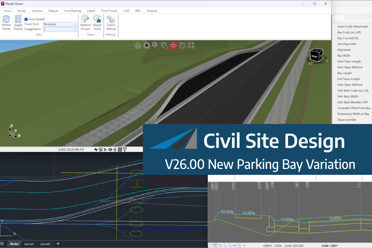
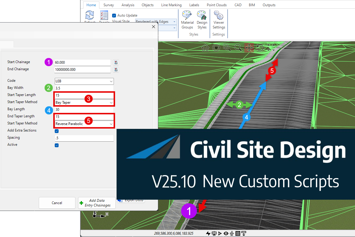
We know parking bays come in all shapes and sizes, and that many of them deserve an independently designed string (with cross sections attached to the string to describe the kerb shape of the parking bay). For those parking/bus or widening bays that can be readily described with cross section edits, we’ve got you covered […]
Non-linear design is when a typical, cross section-based design does not generate the intended result. Typically for designs that are non-parallel, such as driveways, car parks, commercial / Industrial, residential & retaining wall projects. In this webinar, our expert, Jonathan Taylor will show you how to use the Civil Site Design tools to tackle these […]
The Civil Site Design Driveway Checker can be used to assist designers with determining clashes on existing & proposed Civil Site Design project designs. In this webinar, our expert, Jonathan Taylor, will be focusing on using the Driveway Checker to check B85 & B99 vehicles over different crossing points on the project, and exploring the […]