Modern survey equipment now stores more identifiers for a point than just a single integer value. Users can opt to identify the point using an alpha-numeric input. An alpha-numeric point is made up of a combination of alpha characters (eg : A, B, C) and numeric values (1, 2, 3, Etc). A common application of this is to to create a point number with the initials of the surveyor doing the survey and the point number they are at (eg: JH0001).
When surveyors convert the observations into coordinates (for coordinate file import into Stringer) often the alpha-numeric value is input as the Point Number by default. This can result in unexpected behaviour since Stringer is looking for an integer for the core Point Number property.
Depending on your CAD environment, there are two different ways to deal with this:
- Civil 3D: when importing the file of points, set the ‘number’ field in the file to apply to the Point Name in Civil 3D. In the absence of an integer point number in the input file, Civil 3D will automatically assign them and increment them sequentially
- AutoCAD and BricsCAD: you need to set up your Stringer environment to include and use an equivalent ‘Point Name’ field both at the time of import and as a point property on each point.
If you are an AutoCAD or BricsCAD user, read below for the full setup and import process for importing alpha-numeric ‘point numbers’.
Stringer Topo Setup in AutoCAD and BricsCAD
Stringer Topo supports the addition of user defined Point Properties to any COGO point. Additional Point Properties can store any alpha-numeric input, so you could add extended property information to describe the type of tree you are picking up, condition of a manhole or, for our requirements, a Point Name. Any point property can be used for display of point label information in a drawing, can be included in an export table and can be populated during point file import.
So, if you are importing coordinated point data using the Import Points command you can control how the data is imported. If you treat the alpha-numeric point ‘number’ as a different Point Property (eg: Point Name) to the Number, this lets Stringer assign integer values to the points and add the survey linework and breaklines as expected.
There is some once-only setup to automating this process, as we detail below. In summary, you change the following:
-
- Point File Formats: Point File Formats can be used to interpret a point description (splitting it into a Code and String Number for example) and import/export data (describing what Point Property is represented in each field of data). You set up Point Properties to be included in the format and map these to the fields in an import file.
- Point Styles: Point Styles manage both the display of the point and the Point Properties assigned to the point. You set up Point Properties that can be stored on the point and you can represent these point properties in the label (attribute text) components.
- Point Code Sets: Point Code Sets control which Point Styles are assigned to points at the time of import, based on point description. You may with to create a Point Code Set that specifically assigns point styles that use a ‘Point Name’ property, if apha-numeric point identifiers are only used on some projects.
Point File Formats
To support alpha-numeric inputs, add a Point Property of ‘Point Name’ to the Property list, then modify (or create a new) import/export format to use it when importing a Point File.
1.Start the Point File Formats command
2. Select the Format you wish to modify (By Default this will be P,E,N,Z,D), or click on Add Format to make a new one
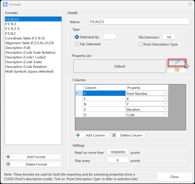
3. Open the Property List editor, as shown below:
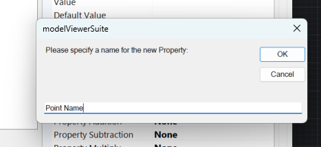
4. In the form that displays, click on Add Custom Property. Name the new field called Point Name and click ‘OK’. The newly created Point Property will now be added into the list.
5. Click on the Apply button. There is now a Point Property available to map to a Column in your import/export table.
6. Usually, your first column is set to reference the Point Number property for a point (which must be an integer). Select the Column that references the Point Number property and replace it with your newly created ‘Point Name’ property: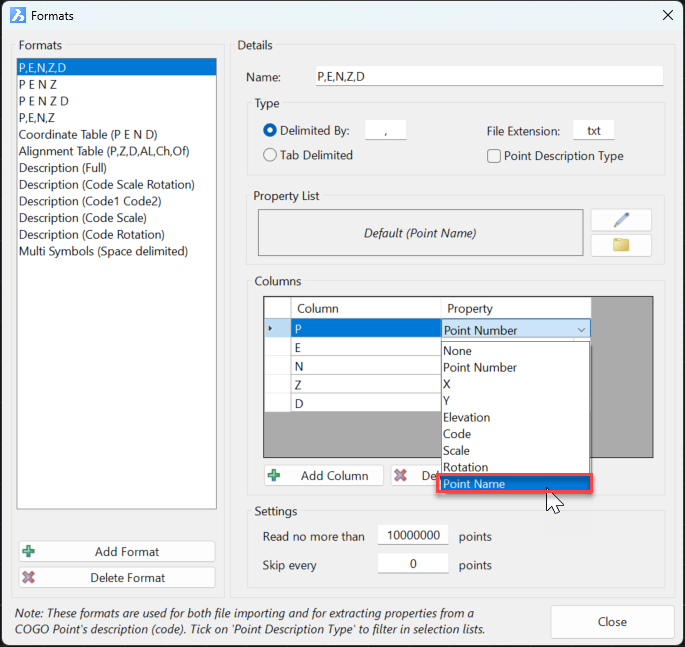
You can now close the form and use this Point File format during point import.
Note: When a Point Number property is not assigned during the import process, the software will automatically assign the next available point number to the first point imported, then increment the point number for each subsequent point.
Modifying Point Styles
When the points are imported, they will be assigned a Point Style. The Point Style controls what Point Properties can be stored on the point (eg: Easting, Northing, Point Name,etc) as well as what displays textually on screen.
Note: It is important that each Point Style include the same Point Property field, to store the incoming data.
Below are the steps for adding a ‘Point Name’ point property to Point Styles
1.Start the Point Styles command
2. Select a Point Style to edit or create a new one
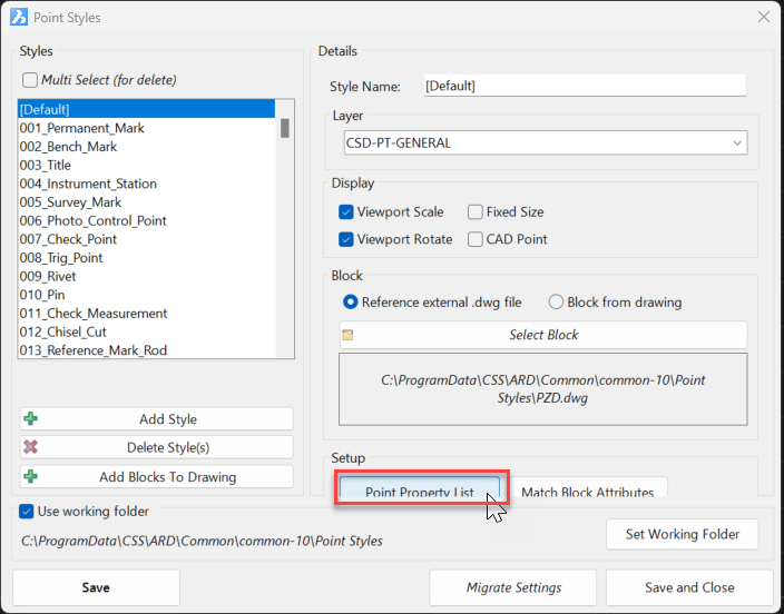
3. Under the Setup heading click on Point Property List to add the ‘Point Name’ point property:
4. In the form that displays, click on Add Custom Property. Name the new field called Point Name and click ‘OK’. The newly created Point Property will now be added into the list.
5. Click on the Apply button. There is now a Point Property available to receive input for ‘Point Name’, and (if required) to use in the labelling of the point. Each Point Label Style consists of a block which (optionally) includes Attribute Text. You can set any Attribute Text object to read data from a Point Property:
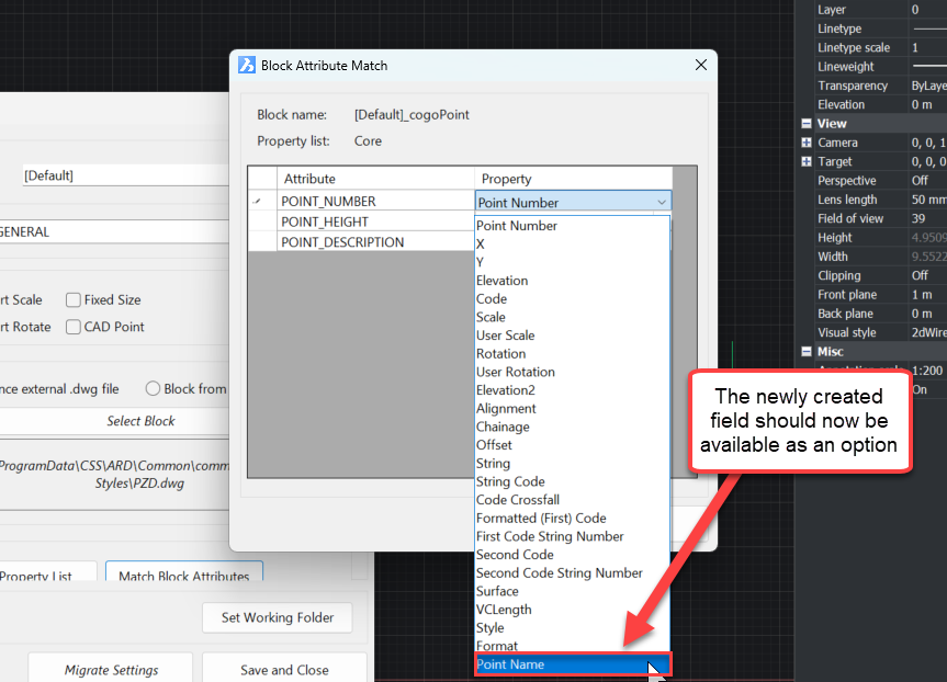
6. From the Point Styles form, under the Setup heading, click on Match Block Attributes to assign the ‘Point Name’ point property to a text attribute. You will see a list of attribute text items listed on the left, and the corresponding Point Property on the right.
7. Change the input of Point Number to Point Name if you want to display the alpha-numeric point ‘number’.
8. Apply the changes, then save and close the Point Style form.
With these two settings adjusted, you can now use Import Points to import a name instead of a number to describe the point, and you can display this point name in the drawing.
Note that editing Point Styles and Point File Formats is saved into your Stringer Settings folder directly, so it’s set up for all future surveys.
Importing Points!
When you next run the Import Points command you can control the point properties via the Point File Format you select (interpreting the input columns of data) and the Point Styles you create for each point (controllable via the Point Code Set.
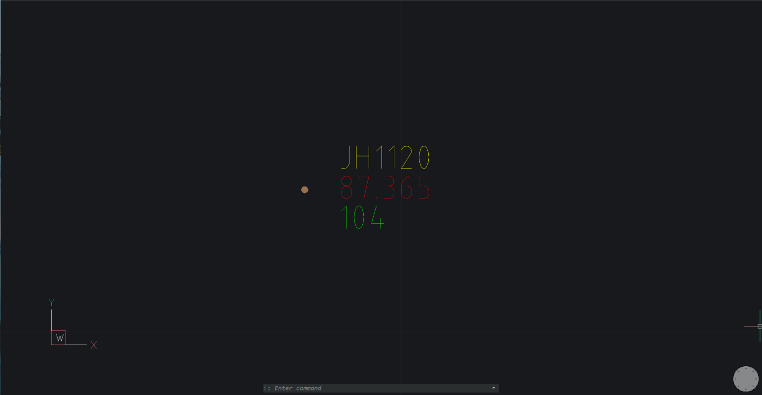
See an example below of the outcomes:
1. Start the command Import Points
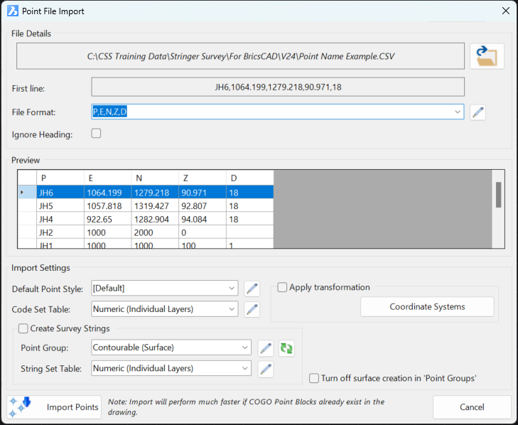
2. Select the browse option and select an input file
3. Set the File Format to match the Point File Format you have edited: Note that the first column is now reading alpha-numeric inputs into the Point Name (not the point number) field.
4. Click on Import Points If you dig into the Point Groups you will find that a point number has been automatically assigned.